Centroid CNC control sales, service, training and support
The following are summaries of various tech support issues I have been called upon to solve in recent years. It is my hope that these may help others more quickly resolve related problems. Be aware, however, that many different problems can have superficially similar symptoms.
The "Slimline" M400 console, introduced ca. 2016 for MPU11-family controls, has four USB ports on the right side. These are extensions, plugged into a USB hub inside the console. That USB hub is mounted to the PC panel, behind the LCD display screen. The connections to the USB hub are most easily reached by removing the jog panel face, as they face towards the jog panel opening in the enclosure.
Sometimes after installing this type of console, one of the USB ports will not work (usually the bottom-most, if you plugged in the extension cables in order). Removing the jog panel and reseating the USB cables will often resolve the problem.
The cause is that the CPU connection (8-pin 0.100" KK type plug) on the jog panel interferes with the bottom-most port on the USB hub, and sometimes causes the extension cable to be partially dislodged when the jog panel is reinstalled.
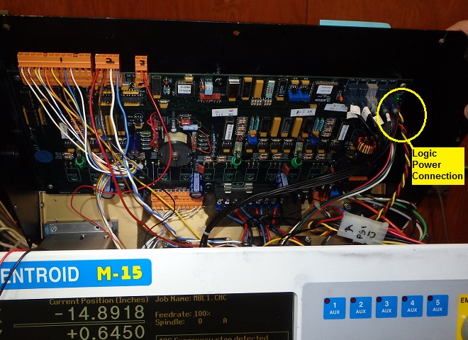
Two customers with late-model M15 controls (M19-9 and M15-10, both from 2001) reported intermittent false "407 ... Limit Tripped", "406 Emergency stop detected" and (most tellingly) "436 Servo drive shutdown" messages.
The messages would appear in flurries, often reporting all six limits plus Emergency Stop all at once, then immediately reporting "Limit switch cleared" and "Emergency stop released". The condition seemed to come and go at random, but became progressively more frequent.
The cause appears to have been poor electrical contact at the logic power connector near the front right corner of the drive board, inside the top cover of the M15.
This connection carries 5VDC and 12VDC power to the drive/PLC board. Intermittent loss of the 5VDC supply causes all PLC inputs to report open.
Treating the plug and header with electronic contact cleaner appears to have resolved the issues. For a longer-lasting solution, it would probably be wise to replace the four-pin plug with the high-pressure version of the 0.100 KK connector.
A customer reported that the effective cutting depth of his tools was varying from part to part. He would re-measure the tool height offset of affected tools, and get offset measurements which varied by as much as 0.015" in common cases, and 0.061" in one case.
On site, we found that there were metal and plastic chips on the tool holder tapers, in the spindle taper, and packed around the drawbar's retention fingers.
The air flow for the taper-cleaning air blow was minimal (barely audible, difficult to feel). We opened up the flow valve for the air blow several turns, to obtain normal chip-clearing functionality.
On the E216 Maximill, and probably most other Atrump VMCs, the flow valve is on the front of the drawbar assembly, behind the head covers. For access you need to remove the side cover from the head. That is easier to do if you have a 4mm hex key on a long extension, for reaching the screw or screws which secure the inside bottom flange of the cover to the head casting.
Another professional field technician reported to me that one of his customers was experiencing false "407 Y axis limit (#3) tripped" messages.
On this machine, like many Atrump VMCs, the X and Y limit switch cable runs through a plastic conduit underneath the saddle. It is tied to a flexible steel strip, which guides the conduit to the rear of the machine.
On this customer's machine, the steel strip had broken at the bend, and the broken end had then cut into the conduit and into the cable inside, severing the signal wire for the Y- limit switch.
The flexible steel carrier can sometimes be inspected from the back of the machine, by removing an access panel and looking in underneath the Y axis way covers.
A customer with a year 2011 M400S control, with Glentek DC servo motors and a DC3IOB drive unit, called. He was getting persistent "411 Y axis full power w/o motion" and "410 Y axis position error" stall messages, which he determined were due to motor failure. The Y axis servo motor had lube oil inside, due to dripping from the X axis ways and ballscrew, and the failure of the machine builder to provide a drip cover over the motor.
His original servo motors and cables were "direct-wired": the power and encoder cables enter the motor back cap via gasketed entries under an aluminum block, and inside the back cap are plugged into pigtails from the armature and encoder.
The only motor I had available to ship immediately had an MS connector (military style cannon plug). I removed the MS connector assembly, leaving the motor with the same Molex connectors inside as his original direct-wire motor had.
When he installed the motor, he reported that the Y axis would only move in one direction. I initially assumed this meant that there was no motion at all when he tried to move the other direction; I later learned that the actual symptom was a runaway, in the Y- direction, whenever he tried to move the axis in either direction. In either case, this sounded like a failed servo amplifier. Such failures are common when motors have been contaminated from oil or coolant leakage.
In fact, the problem was only the polarity of the power to the motor armature. When I got on site and swapped the plus and minus motor leads, the Y axis moved both directions, under control and without errors.
Two important lessons:
The bottom line: when faced with motor runaways immediately after changing a motor, try swapping the power polarity before you go on to any other possible causes.
A customer could not consistently load files from, or save reports to, USB thumb drives, in spite of trying several drives of different makes, including the recommended SanDisk Cruzer.
An "a:" entry would appear in the file menus, but when he browsed to it he saw files from his internal ("c:") drive. If he left that USB drive plugged in, and plugged a second one into another USB port, then a "b:" entry would appear in the file menus. When he browsed to it, he saw the contents of the first USB drive!
The cause turned out to be corrupted structure on the internal ("c:" drive) file system. In particular, there was a hard local directory named "a" in the /cncroot directory. This /cncroot/a was in the way of the default link location for auto-mounting USB drives. When I removed the /cncroot/a directory, then he was able to access all his USB drives normally.
The customer initially got "411 X axis full power w/o motion" and "410 X axis position error" any time he tried to move the X axis. He could jog the Y and Z axes normally.
On inspection, he found that the first axis fuse on his SERVO1 drive was blown. He replaced the fuse, but the new fuse blew again as soon as he started up the control and released Emergency Stop. With power off and leads disconnected, he measured continuity between the upper (load-side) fuse clip and terminal 9 (VM-, aka "GND"). This means that there was a short from VM+ to VM- with a fuse in place. Clearly one or more of the MOSFETs were shorted through.
While waiting for a swap-out drive from Centroid, I advised that he go through the basic motor checks on the X axis motor, described in Tech Bulletin 155; and that he also carefully inspect the servo motor power cable. He did not notice anything alarming.
When he received and installed the replacement drive, it almost immediately failed in the same manner as the first one.
Once I came on site, I found that the original motor had no direct short, but that there was only 25KΩ resistance between the armature power leads and the motor case (chassis ground). There should be no connection between the armature and case ground. TB155 suggests a tolerable minimum of 100KΩ.
I installed a new servo motor on the X axis, and installed a second replacement servo drive.
The failed motor was a Reliance/Electrocraft E728-series. There was a significant amount of black residue visible inside the motor case. This may have been carbon dust from worn brushes, or may have been external contaminants that had worked their way in.
I measured about 75KΩ from armature to case on the Z axis motor, and about 250KΩ on Y. I advised getting the failed X motor rebuilt and using it to replace the Z as soon as possible.
If you have a machine with Electrocraft E728 motors, take the time to disconnect the motor power leads from your servo drive and measure resistance to chassis ground. If any are less than 100KΩ, you should get the motor repaired or replaced before it takes out your servo drive.
A customer with two DOS-based M400 controls reported that he would sometimes get a "Stack Overflow" message when he pressed F6/Edit; the display would then return to the CNC7 main screen, but the console would be locked up and he would have to cycle the power to recover.
The controls were networked to a CAD/CAM computer in the office, running Windows XP. The controls were running MS-DOS, using the Workgroup Connection NETBEUI client to access shared files on the Windows system.
Per the customer's preference, Machine Parameter #4 in the Centroid controls was set to zero. This means that CNC files loaded from a network directory are not copied locally: they are accessed over the network whenever needed. Thus when he presses F6/Edit, the editor is opening the file on the Windows computer, over the network.
Most of the time that worked fine. We found that, when the error appeared, it was because the folder sharing options on the Windows system had been changed. In the folder Properties box, under Sharing, there is a checkbox stating "Allow network users to change my files". If that box was checked, the edit feature worked just fine. However, that box would periodically get un-checked for no apparent reason. When that happened, then the editor would crash with Stack Overflow.
A customer with a 2006 E320 reported that, after a fairly hard crash, the spindle would not orient for an automatic tool change.
At the point the spindle was supposed to orient it would spin, slow to a stop, oscillate back and forth a few degrees for several seconds, then spin again and repeat over and over. Eventually the PLC would cancel the process and report "9037 ATC M6 PROCESS CANCELLED" or, in at least one case, "9010 ATC ORIENT TIMEOUT".
The RPM display in the status window continued to report stable and accurate speeds when the spindle was running steadily (with Parameter 78 set to 1, so that the displayed speed is the speed read from the spindle encoder). This showed that the spindle encoder was still coupled and working, and at least had a reliable connection on the A and B channels.
I had him execute an M19 (spindle orient) from the F3/MDI prompt several times. In at least one case, it eventually stopped and held at the correct position. This showed that the spindle encoder orientation was still correct, and that the index pulse was working at least some of the time.
Finally, I had him check the tension of the drive belt between the main motor and the spindle. This turned out to be the problem: the motor had slipped, causing the belt to be a little loose. This introduced enough slop between the motor and the spindle that the Delta spindle drive could not reliably hold position: it would see the index pulse and try to stop and hold, but the encoder position (belted directly to the spindle, and separated from the motor by the (loose) drive belt) kept bouncing around.
Once he retensioned the main drive belt, the problems went away and the machine could again orient the spindle on the first try.
A customer with a 2006 Maximill with an M400S (DC servo) control reported he was getting a "410 Y axis position error" stall while trying to home. All axes would jog okay in all directions.
Further inquiry showed that the Y axis was overrunning the Y+ limit switch and stalling against its hard stop.
The limit switch circuit remained closed (Green on the Alt-I PLC diagnostic display) even with the switch plunger fully depressed.
At my prompting, he took the cover off the switch body. I expected he would find a broken contact block or something like that. Instead he found the switch body full of coolant. Evidently the coolant was sufficiently conductive to keep the limit switch circuit closed even as the switch contacts separated.
He cleaned and dried the contact blocks and switch unit, and verified that the switch once again worked correctly as a limit and home.
The X axis switch body (which is above the Y switch, and connected via the black plastic conduit) was clean and dry inside. Evidently the coolant in the Y switch body was either getting in the cover or (more likely) getting in the conduit fitting around the outside of the conduit.
He applied sealant and self-fusing silicone tape liberally to the cover plate seam and to the conduit and fittings. Time will tell if that keeps it dry inside.
A customer with a 2009-model Uniconsole-2 M400 reported an apparent motherboard failure. I set up a replacement motherboard for testing, in preparation for either sending it out to him or installing it in his console myself. Although the customer's system has CNC10 software version 2.64 on it, I plugged in a flash card with software version 2.38. After all, I just needed to test whether the motherboard would boot up and run reliably.
It did boot up, and I had no problem navigating the CMOS setup screens.
However, once Linux and CNC10 started up, system response was very poor. Processing was very slow, and response to the keyboard was intermittent: sometimes the keys would take effect after a significant delay; other times they would not take effect at all.
I shut down, plugged in a flash card with CNC10 version 2.64, and booted up again. This time everything responded normally.
Reviewing Centroid's Tech Bulletin 218, it is evidently known that Gigabyte M61 motherboards (and perhaps other motherboards used since 2008) require CNC10 v2.60 or newer.
This issue could come up if a replacement motherboard is needed on an earlier system which was running software older than v2.60. It will not be possible to just replace the motherboard and keep using the old flash card. A new flash card with v2.6x or newer software will be required.
Update: it appears that the Gigabyte M68 motherboard does not have this problem. I have run CNC10 v2.3x on M68M-S2P motherboards several times without difficulty.
A customer called regarding some advanced CNC macro programs he had written.
He was using the #150-series persistent variables to maintain status information about his process, so that the information would be preserved from one cycle run to the next.
However, he found that when a program cycle was interrupted before completion, the values saved in the 150-series variables were those that would have been in place had the cycle finished.
This is because of the control's advance processing. When possible, it reads hundreds of lines ahead in the CNC program, processing the upcoming moves and calculating acceleration and deceleration distances.
The solution is to insert a line which the control cannot process in advance, forcing it to stop and wait, just before the variable assignment. For example:
    IF [#6001]
    #150 = #150 + 1
The line "IF [#6001]" is a complete statement, telling the control that
if PLC Input1 is open (1) when program execution reaches that point,
it should execute the remaining statements on the line. In this case
there are no remaining statements on the line, but that does not
matter. The control still waits for program execution to catch up to
that point before checking to see whether INP1 is open or closed.
Only after executing the IF statement will the processor go on to the
variable assignment.
Note: the above example is for CNC10 and CNC7 control software. On CNC11 systems, PLC inputs appear as system variables #50000 and up (and, for what it's worth, a value of 1 indicates a closed switch rather than an open one). Otherwise, the same concern applies to macros in CNC11. The usual lines would be similar to this:
    IF [#50001]
    #150 = #150 + 1
I sent a new compact flash hard drive with Linux and CNC10 to a customer, as an upgrade to a ca. 1995 Phoenix router. The customer supplied a new rack-mount PC, capable of running the new software, while still having an ISA expansion slot and room for the original CPU7 board.
When he started up with the new software, CNC10 failed to initialize the CPU7 board. The error messages were:
  DSP not responding
  Error occured sending line 295
  102 Error initializing  CPU...cannot continue
  Return code 63
The cause was that I failed to delete the cnc8.hex file from the /cncroot/c/cnc10 directory when I set up the new flash card. That file is used with CPU7 boards from approximately 1998 onwards (boards with the 2101 DSP chip installed). Earlier boards have the less-capable 2105 DSP chip, and cannot use cnc8.hex.
The solution is to remove the cnc8.hex file, so that the control software falls back on the smaller cnc7.hex file, which is compatible with the 2105 DSP.
Note that the line number in the second message line ("Error occurred sending line nn") will vary with different software versions.
A customer using (Linux-based) Intercon version 2.64 reported that Intercon was not automatically reloading their conversational programs when they returned to Intercon after Posting.
Normally, when you create a new program, or load an existing one, and press F10/Post, Intercon includes comments in the G code file which allow it to locate the source ICN (conversational) file in the future. Thus if you have an Intercon-generated CNC program loaded, and you return to Intercon (e.g. F5/CAM, F1/ICN), Intercon will load the conversational file for that program and present it for editing.
It turns out that this feature fails if your part program name includes space characters (e.g. "My Part" instead of "MyPart").
In general, your life will be easier if you do not include space characters in your program names. You can use underscores or hyphens if needed (e.g. "My_Part" or "My-Part").
A customer with a small lathe called. His control is a T15 with the Aaeon PCM6890 (PC104-bus) motherboard and DOS-based control software version 8.23.
He had begun getting increasingly frequent startup failures. The motherboard would boot up and start the CNC7 software; CNC7 attempt to initialize the CPU7 board and would fail with the message "Timeout: 64180 not responding".
That message generally means that the PC-based CNC7 software was unable to get a response from the main processor on the CPU7 board (across the card bus: PC104 in this case, ISA or PCI in other cases).
I had him unplug the wired devices from the CPU7 (jog panel and encoders) to see whether an external device might have been interfering with CPU operation. That did not appear to be the case, which left the CPU7 and the motherboard itself as possible causes. I lent him a different CPU7 board; with that board in place the problem continued. He then obtained a used motherboard assembly from Centroid. Even with the replacement motherboard and CPU7 in place he still had startup problems.
Finally, he decided that the pin engagement in the PC104 bus looked too shallow, and trimmed about 1/16" off of each of the 1" hex standoffs that separate the CPU7 from the motherboard. With the shortened standoffs the control started up and ran fine, even with his original CPU7 (he did not report whether he tried swapping the motherboard back).
This was a new one to me. There are between 1200 and 1500 PC104-based Centroid controls in the field, generally with the same pin dimensions. This is the first I have seen startup problems positively attributed to pin engagement. There has been some variation in the use of plastic washers over and under the 1" standoffs; it is possible that this customer's control was assembled with thicker washers in both positions.
A customer with the TT1 tool detector called to report that his TT1 was intermittently failing to detect the tool tip on contact. In all cases he had stopped the move before overtravel damaged the TT1.
He had an older TT1 which had been damaged by overtravel several years previously (failure to plug the unit in). He tried using that unit on the same cord, and it seemed to detect okay. Thus we suspected the problem was internal to the newer TT1.
Centroid was skeptical of that. The TT1 is a simple continuity device, with direct contact between the plunger and the inside end of the cord plug (both isolated from the base). There are no wire connections inside. It would be very unusual for it to fail to make contact, short of major mechanical damage (e.g. due to a crash).
Further testing and inspection proved Centroid right. The problem was in the cord, which had been stressed and had broken at the back of the plug pin. This connection is covered by heat shrink. The heat shrink was holding the wire together so that it made intermittent contact.
In order for the TT1 to detect the tool there must be continuity from the socket on the side of the TT1 to its plunger; and there must be continuity through the cord from pin 5 of the black AMP connector to the single pin which plugs into the side of the TT1. These components can be tested independently with a multi- meter. The cord can also be tested using the PLC Diagnostic display on the control (Alt-I). The probe input (often INP15, but see Machine Parameter 11) should close (turn green) whenever the cord is plugged in and its tip is touched to the machine table or frame.
A dealer called to report that one of his customers, after replacing a failed motherboard in a ca. 2005 M400S console, had gotten the "This demo control has expired" screen on startup.
That message normally means that the time-limited demo mode on a new control has run out, and the permanent software unlock codes (specifically the overall unlock in Parameter 298) have not yet been entered. It can also appear if the Centroid CPU board is swapped out, because the unlock codes are keyed to each individual CPU board.
In this case, however, the customer still had the permament unlock codes in place (as they had been for several years) and had not changed the CPU board. He had replaced the PC motherboard in the console, but had reinstalled his original Centroid CPU10 board.
In order to verify that there had not been an unreported CPU10 change, I asked the customer to check his system key by pressing F2 at the "demo expired" screen. This should ordinarily display the 9-10 letter code for the system key on the CPU board. In his case, it just said "error - press a key", indicating that the control software was unable to retrieve the system key from the CPU board.
To make a long story short, it was ultimately found that the customer had plugged the IDC connector from his jog panel into the CPU10 board's "JOG" header backwards. Most such IDC connectors are keyed to prevent this, but evidently he received one with no key. The crossed connections between the CPU10 and the jog panel evidently suppressed the section of the CPU10 which holds and reports the system key, among other functions. Fortunately it appears that no permanent damage was done. He reconnected the jog panel correctly and everything resumed proper operation.
Customer e-mailed to report intermittent "436 servo drive shutdown" errors, also intermittent "410 _ axis position error" and "411 _ axis full power w/o motion" stalls. The stalls could occur on any axis. Sometimes the machine would run for a while without errors; other times they could not even home the machine after power-up.
The first thing to try in this situation should always be cleaning the servo logic power supply connections (see http://www.cncsnw.com/ServoLogicPM.htm). In this case, the customer had already cleaned the connections, but the problems continued.
Next he inspected the supply itself (a Toko supply with the alternate Revolution AC connector: see http://www.cncsnw.com/Drives.htm#SERVO1) and wrote:
"It looks like the Toko logic card on the back of the servo drive is cooked. The center of the card is black and a couple of the solder points are melted and floating. Can we replace this card?"
I supplied a replacement power supply, with the appropriate plugs. Since the replacement supply (a MeanWell PT45B) had a different mounting hole pattern, I provided some wire ties and 1" self-adhesive anchors to secure it to the back of the drive. An adapter plate with both hole patterns would have been better, but there was not time to fabricate one. Four 1" wire tie anchors should be sufficient to hold the supply board in place for many years, as long as the surface is cleaned with alcohol before the anchors are applied.
With the new logic power supply in place, the machine homed and ran with no further errors.
I agreed to upgrade a 2003 M400S control (originally DOS-based) to the newer Linux-based CNC10 software.
The console originally had an MSI MS-6368 motherboard, 1.2GHz Celeron processor, and 64MB memory (http://www.cncsnw.com/motherboards.htm#MS6368). The motherboard and processor were sufficient for running the current Linux and CNC10 software (v2.64 at the time of this upgrade), but the 64MB memory was inadequate.
I plugged a 512MB PC133 DIMM into the second DIMM slot, leaving the original 64MB PC133 DIMM in place.
I then removed the old flash card (solid state hard drive) and plugged in one containing CNC Linux and CNC10 v2.64. The boot process hung up at "booting the kernel...".
I then tried a flash card containing CNC Linux and CNC10 v2.38 (which uses an earlier Linux kernel). This time it proceeded further, but hung up randomly at several different points in the process: once after "freeing unused kernel memory...", once while starting up the X Window system, once while initializing USB support, etc..
I then removed the 64MB DIMM and moved the 512MB DIMM into the first slot. Both Linux versions booted up and ran fine. I completed the upgrade with version 2.64, and had no further problems.
I had thought that PC133 DIMMs of different capacities would be compatible with each other. That turned out not to be the case.
Customer with 2007-model Uniconsole M400 (see http://www.cncsnw.com/Fieldguide.htm#M400_2002) called: machine was running normally, then quit abruptly. The machine stopped and the screen went blank.
They cycled the power and got a "no signal, going to sleep" message on the LCD display. This indicates that the LCD monitor has power (and therefore that the MATX supply in the console is turning on and putting out 12VDC) but that the PC motherboard is not booting.
The original console motherboard was an MSI MS-7253 (http://www.cncsnw.com/motherboards.htm#MS7253). I stopped by Fry's on the way down and purchased a Gigabyte GA- M61PME-S2P motherboard, Athlon 64 X2 processor, and a pair of 1GB DDR2/800 DIMMs.
On site I powered up the control and found that it initially booted okay. However, the CPU temperature reported on the CMOS Setup screen rose steadily every time I rebooted and checked it. Initially it was 115°F to 120°F, which is normal for these consoles. After 10 or 15 minutes of power-on time, though, the temperature had risen to 150°F. The CPU cooling fan was running, but evidently not keeping up. I tried reseating the fan, but the temperature continued to rise beyond acceptable limits. The console then locked up, and when I cycled the power it refused to boot at all.
I installed the new motherboard with new CPU and memory, powered back up, and tested the system. The new CPU stabilized at around 50°C (122°F). While a little higher than I would like, it showed no signs of rising farther and so should not cause any problems.
I reminded the customer to check and clean the console cooling fan filters frequently.
A customer with an original style M39 pendant (as shown in the first picture on http://www.cncsnw.com/FieldGuide.htm#M39) wrote to report the following:
"The M39 Pendant on our Milling Machine is starting to give some trouble with a few of the buttons. The Y-axis positive jog button and the X-axis negative jog button do not always move the table. Also the .0001" increment button for the pendant hand wheel is also not activating when pushed. Pushing the buttons either lightly or with some force does not work. The only way the three buttons will work is the "squeeze" and hold the pendant with the fingers of your hand just to the left and below the X-axis negative jog button."
I was not available to look at it on site, so I had him ship the pendant to Centroid for evaluation and repair. Not unexpectedly, they found that the inner circuit board had started to separate from the jog keypad board, causing intermittent contact for some of the keys. They plugged the boards securely together and put adhesive on the plugs to keep them there.
This one could have been fixed in the field, but if it were it would ideally have required a new overlay. In this style pendant, it is only the overlay (the self-adhesive plastic sheet with the keys printed on it) that keeps the keypad in place and seals out contaminants. If you peel it up to access the boards (or the emergency stop pushbutton) then you need to clean the mating surfaces thoroughly and either apply a new overlay, or reinstall the old overlay with suitably strong and thin adhesive.
The machine is a 2006 Atrump E320, with a 16-station umbrella- type tool changer, M400 AC-servo control, and Linux CNC10 control software v2.61.
Customer reported that tool change sequence stopped with carousel in, gripping the old tool. The fault message was "9015 ATC UNCLAMP TIMEOUT".
After clearing the carousel using the manual override button on the pneumatic solenoid valve, I had him try removing and inserting a tool using the manual tool release pushbutton. This worked normally, showing that the tool release cylinder was working fine. I had him press Alt-I for the PLC Diagnostic display and highlight INP23, the tool-unclamped switch. We found that INP23 remained Red (open) even as he removed and inserted tools with the manual pushbutton.
Further investigation showed that the tool-unclamped switch had physically come loose: one of its two mounting screws had fallen out, and the switch was hanging down at an angle. As a result, the trip tab on the drawbar cylinder never closed the switch even after moving full stroke.
One the switch was secured back in its correct location the machine once again changed tools without error or incident.
Customer had two Revolution mills: a 1997 model with the old M40-style console, and a 1998 model with Revolution's console and the updated jog panel. Both were still running CNC7 version 5.27 software.
The hard drive failed in the older machine, and they had no backups. Their IT person copied the contents of the newer machine's hard drive onto a new drive and installed it in the older machine, in place of the failed drive. The computer booted up okay, but reported "Spindle drive fault detected", and of course would not home. There was no fault code displayed on the spindle drive.
The spindle drive fault message was due to differences in PLC logic. The older machine with the M40 console used the PLC program "MX0-I3.SRC", suitable for a machine with an RTK2 PLC, spindle inverter, three axes, and the M40-style jog panel. The newer machine used the PLC program "M400.SRC", suitable for a machine with an RTK2 PLC, three or four axes, spindle inverter or reversing contactors, and original M400-style jog panel. Because M400.SRC was intended to work with reversing contactors as well as an inverter, it required a normally-open spindle fault signal (the only auxiliary contacts available on the contactor overload, after the normally-closed contacts are used to interrupt the coil).
Even if the customer had changed the inverter's fault wiring over to normally-open contacts, there would have been several other problems with the PLC program because of the different jog panel key layouts. There also would have been numerous problems with Control Configuration and Parameters, as in general configuration and parameter values are machine-specific.
I e-mailed backups I had taken from the failed machine in 1998, plus an updated PLC program and a few supporting files. These got the machine back up and running correctly.
The customer did well to get a replacement hard drive working with a copy of the software from the other machine. However, that was only half the job. The other half is to have on hand a configuration backup from the target machine, so that correct PLC programming, configuration and parameters can be restored.
Note that the Utility -> Backup -> CFG feature in version 5.27 and earlier does not do a very complete job. It picks up Configuration and Parameter settings, but it does not back up several other important files. If you are still using v5.27 and want to make complete backups, you should copy the following files from the CNC7 directory, using a DOS command prompt (Ctrl- Alt-X):
You should also copy any *.SRC files from the C:\PLC directory. One of these will be the source file from which your PLC program was compiled, and so will be valuable if you ever need to modify the PLC programming.
Control is a 2005 M400S, with the DC3IO servo drive/PLC unit.
Local technician called:
This appears to be a fairly cut-and-dried case of a blown output on the DC3IO. The main concern is whether it was caused by an intermittent short in the servo motor or motor power cable. The last several tests indicate that the motor and cable are okay. We will send the drive to the Centroid factory for repair and return.
It would be nice to have a clear indication of why the Y axis may have blown, but there is no smoking gun here. The machine is a Series II Bridgeport with quill drive, so Y is the most heavily-loaded axis.
Once the repaired drive is in place I will have him re-run the Drag test on that axis (and preferably on all three axes) to see if something is binding or dragging to cause excessive motor load.
Three months later, with a replacement DC3IO unit in place, the customer has had no further problems. He has not yet found motivation to re-run the drag test.
Copyright © 2015 Marc Leonard
![]()