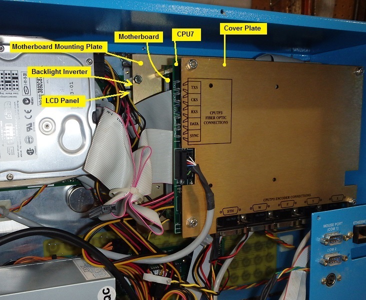
 The motherboard and CPU7 control board are stacked behind the LCD panel.
From top to bottom there are:
The motherboard and CPU7 control board are stacked behind the LCD panel.
From top to bottom there are:
Centroid CNC control sales, service, training and support
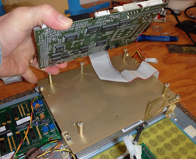
The motherboard and CPU7 control board are stacked behind the LCD panel.
From top to bottom there are:
The LCD backlight inverter is a small circuit board, mounted to the under side of the motherboard mounting plate.
To get down to the motherboard and the backlight inverter, you will need to remove the CPU7 board. The process will be easier if you remove the console from the arm, and remove the front panel from the console.
Unplug the optical fibers and encoder cables from the CPU7 board. Unplug the emergency stop cable from the two 2-pin plugs leading to the emergency stop pushbutton. Unplug the AC power cable from the 3-pin plug leading to the power supply.
Unscrew the conduit nut, then thread the disconnected cables back out through the nut and the opening in the console-back sheet metal.
Hold the console securely and remove the 1/2-13 bolt in the console mount bracket; then remove the pivot sleeve which the bolt passed through. You should then be able to pull the console free of the arm and place it on a bench.
 Remove the four locking nuts. Remove the cover plate. Remove the four
short (1/2") hex standoff posts. Unplug the jog panel cable from the
CPU7 board, noting its orientation (the connector is not keyed).
Then remove the CPU7 board.
Remove the four locking nuts. Remove the cover plate. Remove the four
short (1/2") hex standoff posts. Unplug the jog panel cable from the
CPU7 board, noting its orientation (the connector is not keyed).
Then remove the CPU7 board.
As you remove the hex standoff posts and the boards, keep track of the location and thickness of the plastic washers. There are two different thicknesses. Generally, there will be one set of thick washers (4x) under the CPU7 board, and one set of thin washers (5x) under the motherboard.
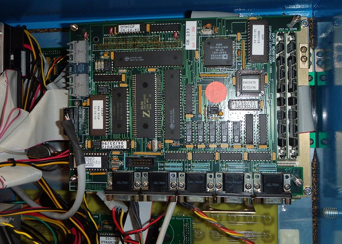
The CPU7 board is mostly held in place by the 104-pin bus connector, so you want to pull gently all around that connector, gradually working it loose. However, the corners of the board tend to hang up on the threads of the next layer of hex standoffs, so while working the pin bus loose you need to periodically free the corners so the board doesn't get flexed excessively.
Set the CPU7 board aside in a clean, safe, and static-free location.
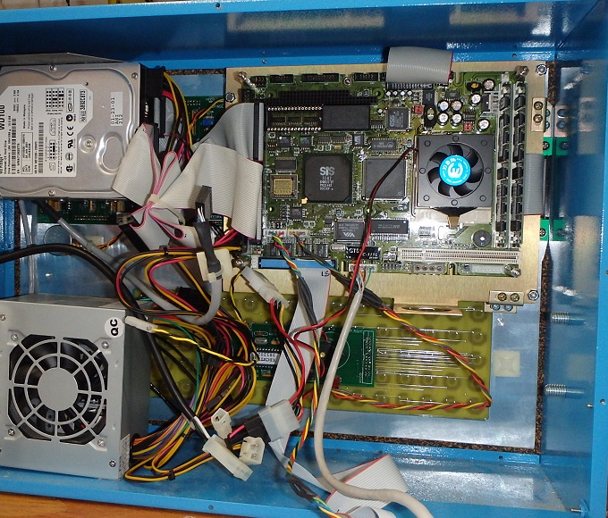 The motherboard is now exposed. If your objective was to replace a
replaceable motherboard battery (e.g. the CR2032 on an Aaeon motherboard),
or to access the CPU fan or memory slots, you can stop here.
The motherboard is now exposed. If your objective was to replace a
replaceable motherboard battery (e.g. the CR2032 on an Aaeon motherboard),
or to access the CPU fan or memory slots, you can stop here.
If you need to remove the motherboard, or access the LCD backlight inverter or LCD panel, it will be helpful at this point to remove the front panel from the console enclosure.
Unplug the DC power connections to the motherboard; to the CPU fan (if any); and to the card cage fan (if any). Unplug the ribbon cables to the hard drive and the floppy drive. Unplug any ribbon cables to serial and parallel port extensions in the console back, and to the PS/2 mouse port, if present.
Remove the twelve 6-32 cap screws from around the console front panel.
Lean the front panel out a few inches; locate the short cable which connects the MPG handwheel connector to the back of the jog panel, and unplug it from the jog panel (or, alternately, dismount the 8-pin MPG connector from the console-side sheet metal).
Separate the front panel from the rest of the console enclosure and lay it face-down on a clean, level surface.
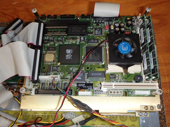
The motherboard is held down by the four tall (1") hex standoff posts, plus (usually) a single 6-32 hex nut midway along the top edge. Remove these and set them aside.
Unplug the keyboard cable from the motherboard. Optionally unplug the hard drive and floppy drive ribbon cables and set them aside.
 The ribbon cable for the LCD panel leads to the "descrambler" board on
the edge of the LCD panel. In many consoles, that cable is permanently
glued into its connector on the motherboard. If it does not want to come
out, don't force it; just unplug the other end from the descrambler
board instead.
The ribbon cable for the LCD panel leads to the "descrambler" board on
the edge of the LCD panel. In many consoles, that cable is permanently
glued into its connector on the motherboard. If it does not want to come
out, don't force it; just unplug the other end from the descrambler
board instead.
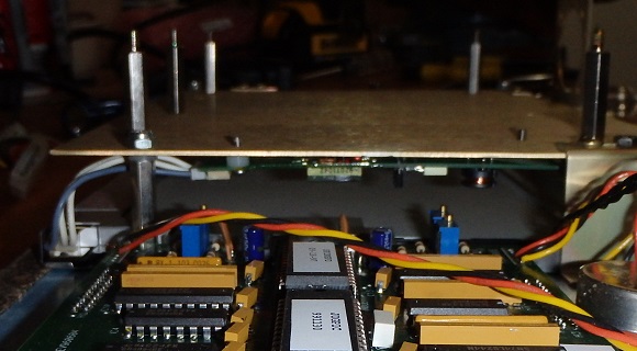 The LCD backlight inverter is mounted underneath the motherboard mounting plate.
It should have a 12VDC supply coming in, usually via a thin brown connector on the near edge (facing the jog panel). The backlight inverter pictured here is a later replacement style, with the 12VDC supply coming in via a thin white connector on the far edge (away from the jog panel).
In either case, the high-voltage, high-frequency AC power to the backlight
fluorescent tube goes out the top end, via a 3-pin white connector.
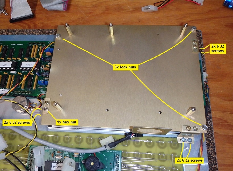 To replace the backlight inverter, you will need to remove the
motherboard mounting plate.
To replace the backlight inverter, you will need to remove the
motherboard mounting plate.
It is simplest to leave the support "legs" attached, and just remove the ten fasteners noted at right.
There is no need to remove this set of hex standoff posts.
Unplug the AC wires from the fluorescent tube, then flip the plate over on the bench to access the backlight inverter.
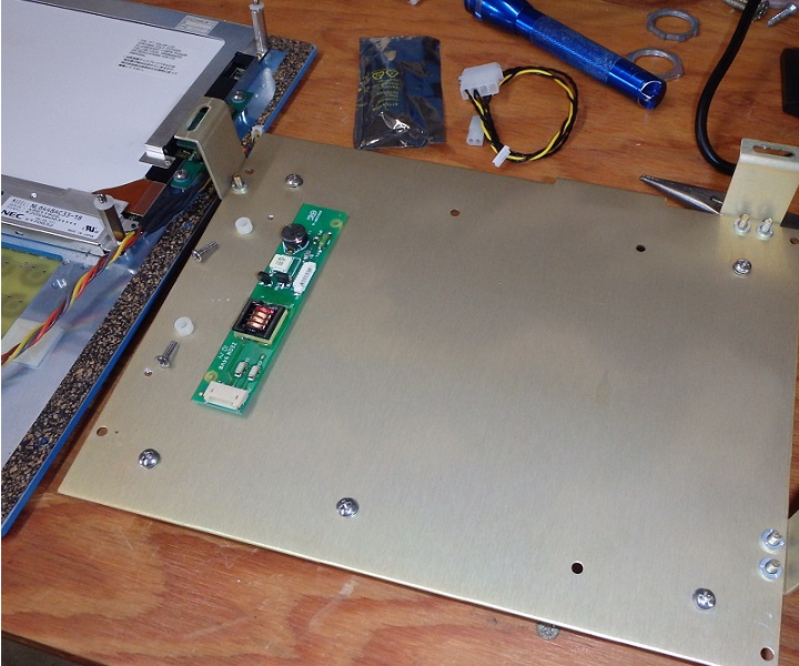 The backlight inverter is secured with two 4-40 screws, through plastic
standoff bushings.
The backlight inverter is secured with two 4-40 screws, through plastic
standoff bushings.
The holes in the backlight inverter board are actually too small for the #4 screws, so the screws will have cut threads in them, and will not fall free even when free of the aluminum plate. Carefully unscrew them from the board, and keep track of the plastic bushings.
Reverse the process to install the new inverter, plug in its connections, and reassemble the motherboard/CPU7 stack.
Take care when plugging the LCD ribbon cable back into the descrambler board, as there is no key or shroud to ensure proper alignment.
Copyright © 2015 Marc Leonard
Last updated 22-Feb-2015 MBL
![]()